Making a raytracer
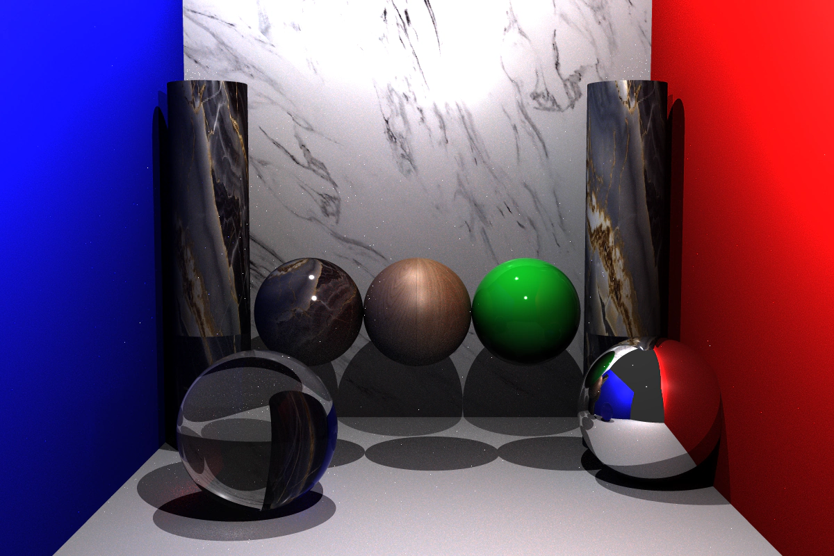
At uni, I chose to take a course in computer-generated graphics. A big part of it was making a raytracer from scratch in C++. It was a very welcome assignment after so many less practical ones. Here is the final result:
But this wasn't my first raytracer. When I first started working with React, I had the (not so) brilliant idea of building one in React.
I used ASCII characters for the shading, with a spinning triangle in the middle. See how it chugs! This is where I got to:
I don't write about university assignments much, but I came away from this project with so much appreciation for the craft that I thought it would be nice to share some milestones and technical details.
I'll only cover the basics here, but the milestones below show some of the magic behind making the actual images.
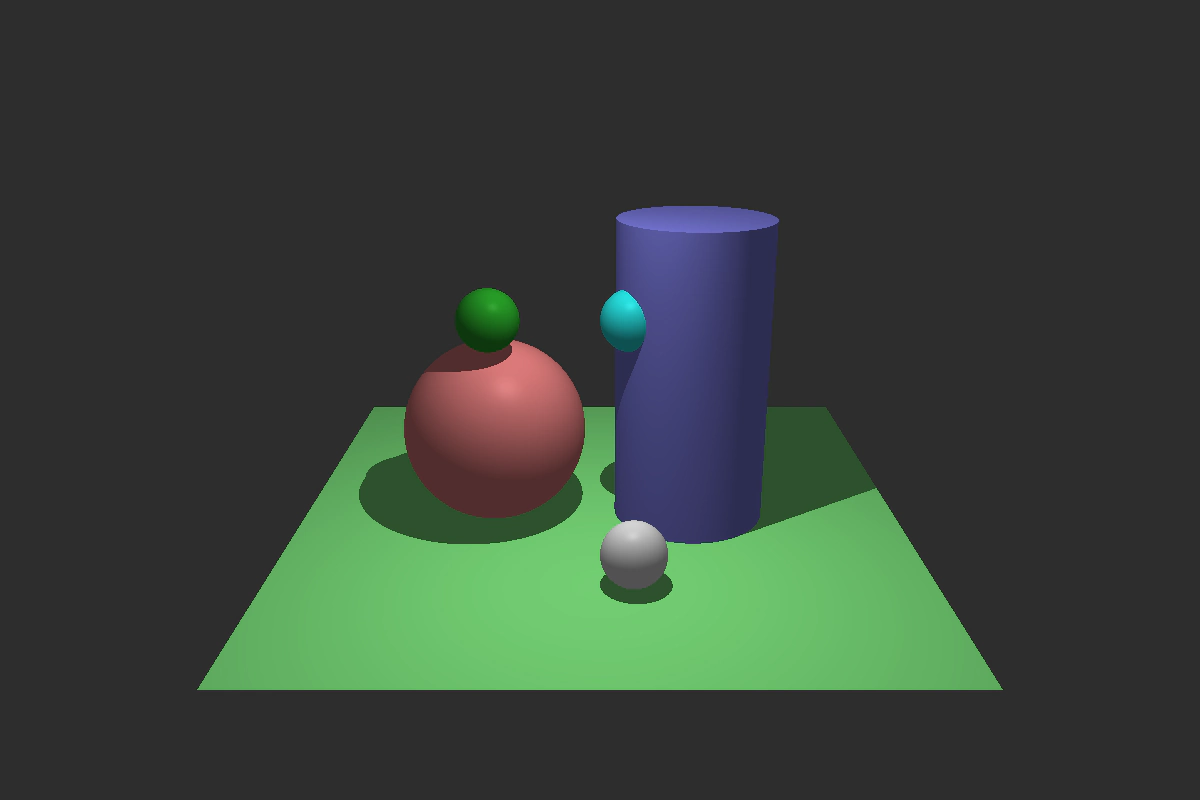
The basic concept of a raytracer is shooting rays from the camera into a scene to create an image. If a ray hits a surface, we colour the corresponding pixel based on the material and the ray's relationship to the surface and lights.

To add light and shadows, you shoot another ray from the intersection point towards a light. If something blocks it, the point is in shadow; if it reaches the light, the point is illuminated.
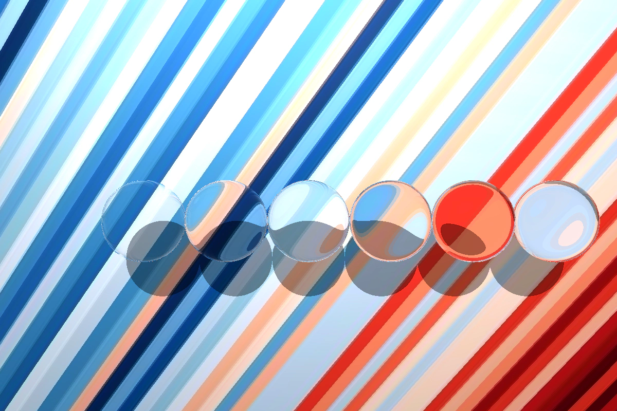
You can make this even cooler by adding refraction: when light bends as it passes from one material into another. In a raytracer, we model this by changing the direction of rays as they enter and leave a surface.
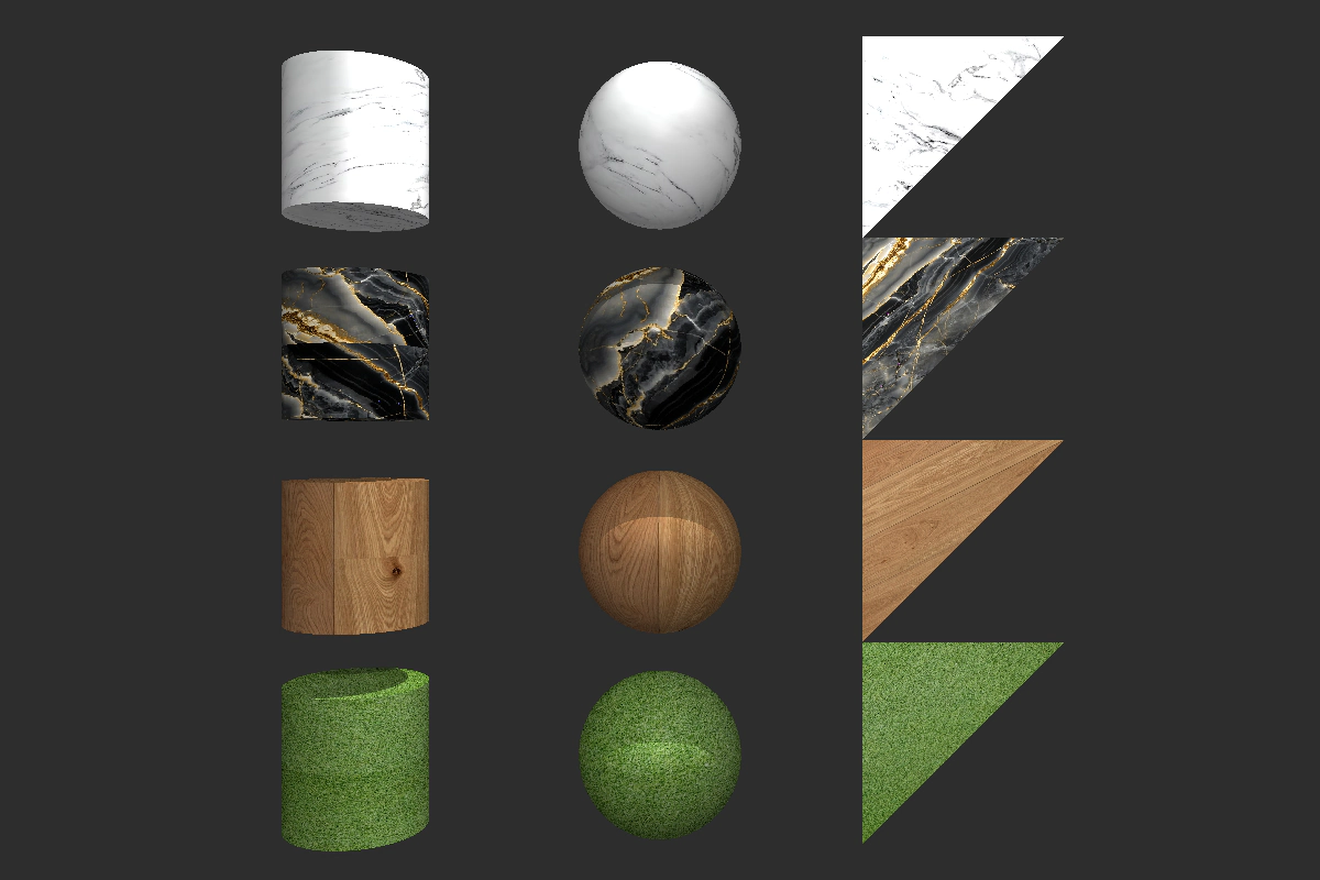
You can take it further with textures. When a ray hits a surface, you look up the colour in a texture map using the surface coordinates at that point.
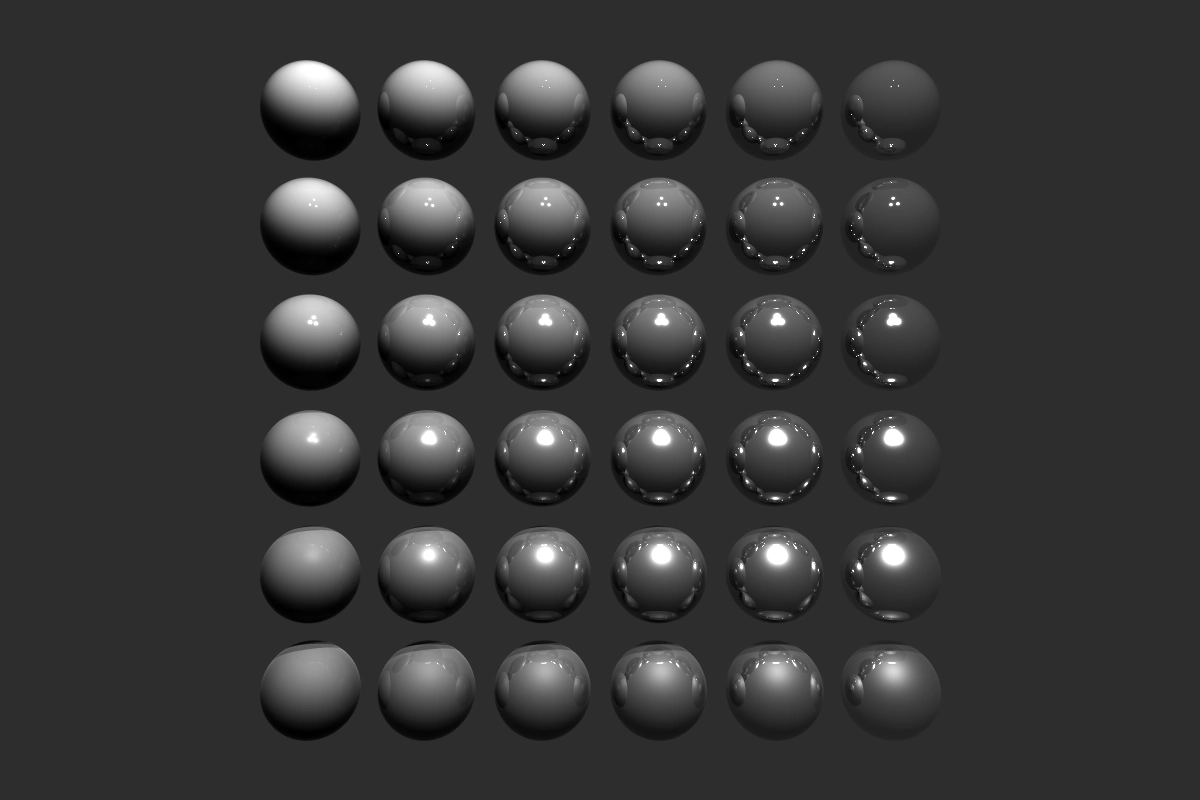
But a material is not just its texture. Different materials have properties you can control, such as roughness and metalness. To simulate them, you tweak how rays bounce off a surface and how their contributions are combined.
If you put this all together, you can make interesting scenes with refraction, mirrors and colour. Colours can even bleed into one another. Notice how the red wall gives the white wall a slight red tint, and how the granite is smoother and more reflective than the wood.
All this random sampling can also create little bright specks known as fireflies. They appear when a pixel happens to use rays that pick up more light than their neighbours. This is possible because the direction of each per-pixel bounce is random.
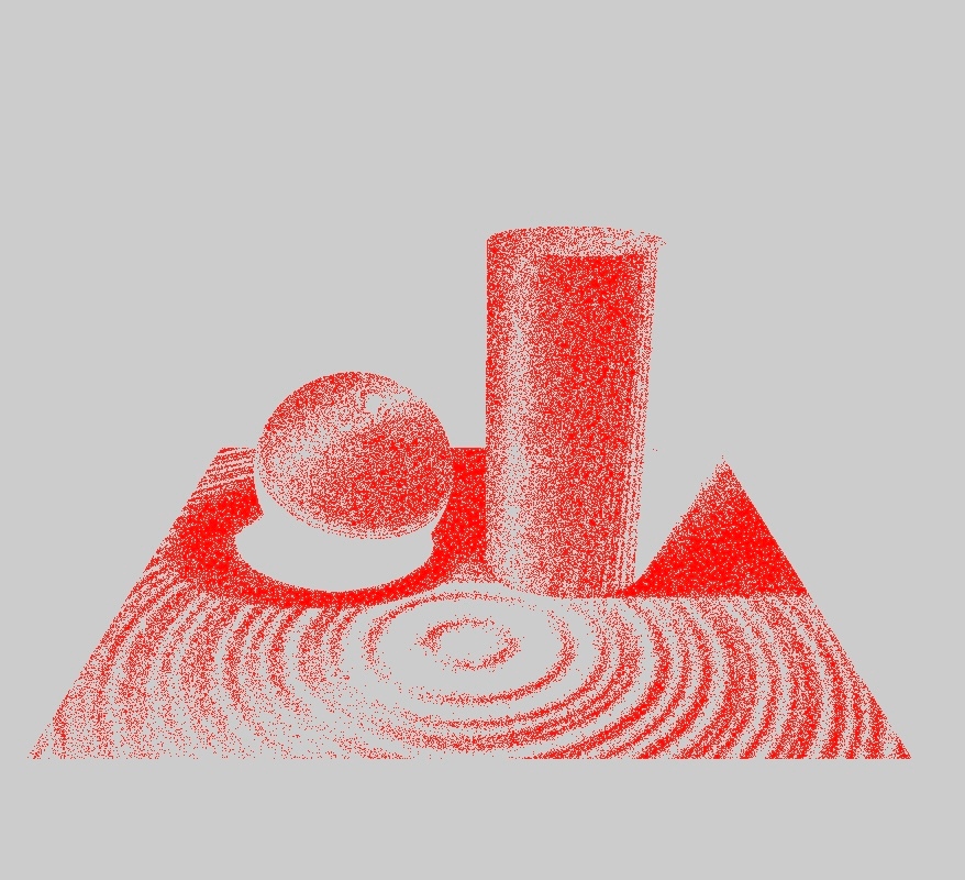
The two renders compared below use exactly the same scene and settings. The only difference is the slight randomness applied to rays as they bounce off a surface. That variation spreads the shadow transition across neighbouring pixels, producing softer shadows without a perfectly sharp outline. Every pixel that differs between the two renders is shown in red.
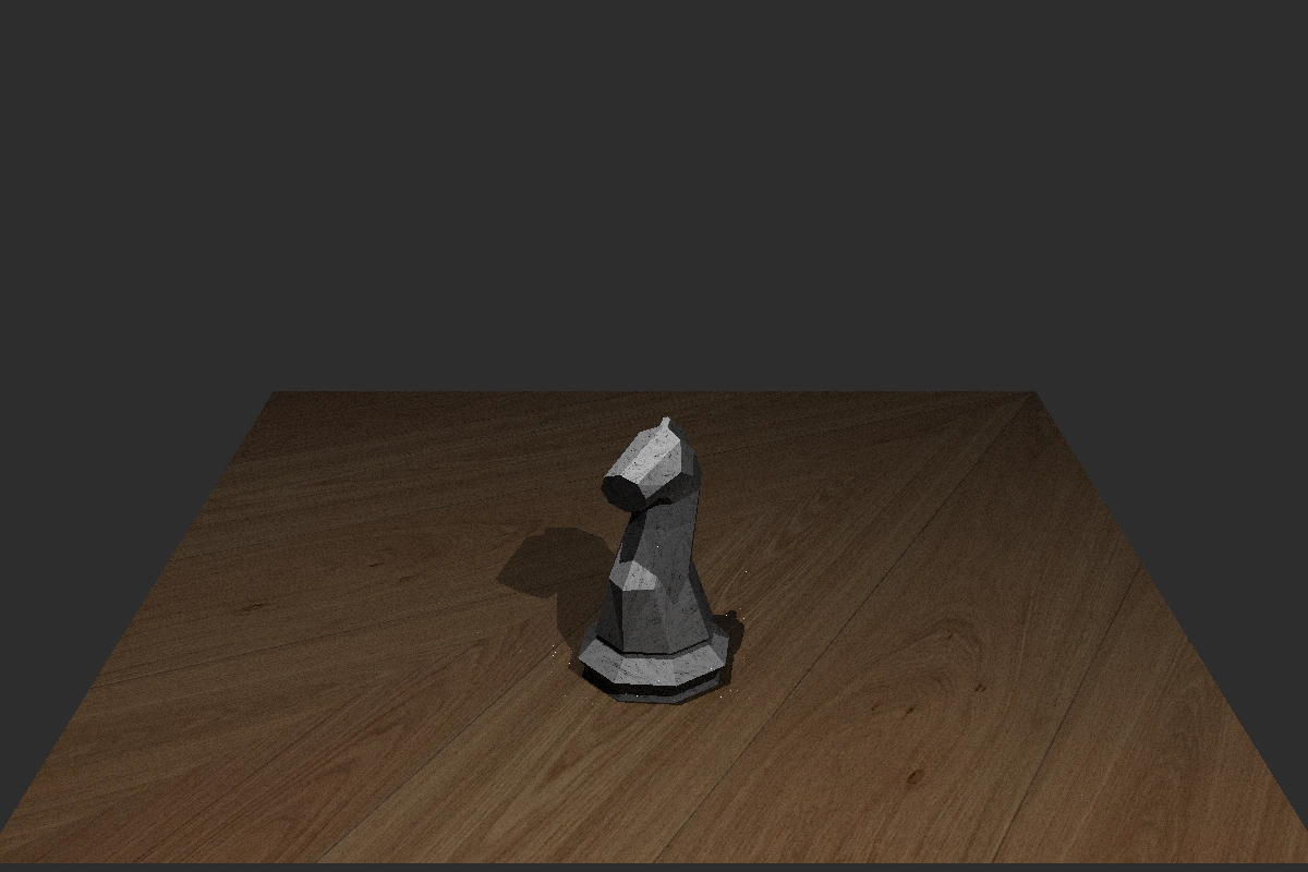
By using many triangles you can approximate almost any shape you want.
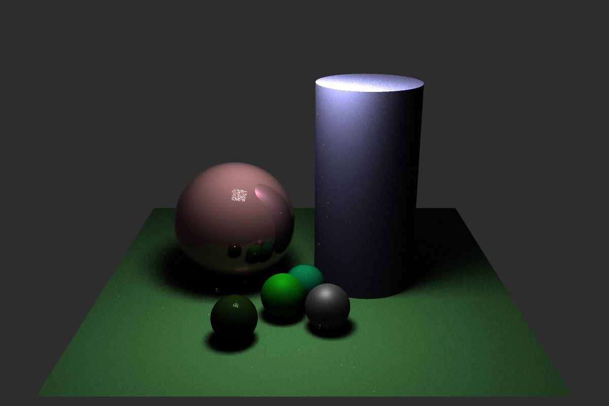
By modelling an area light or a camera aperture, then taking multiple samples, you can create soft shadows and even the depth-of-field effect that cameras with lenses have. Though this increases compute significantly.
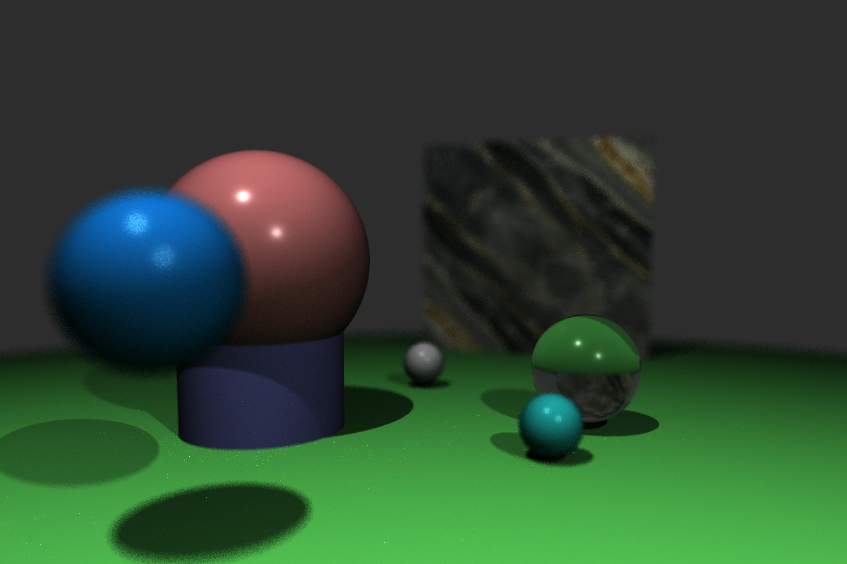
Sampling a moving shape at different positions during the shutter interval can create motion blur too.
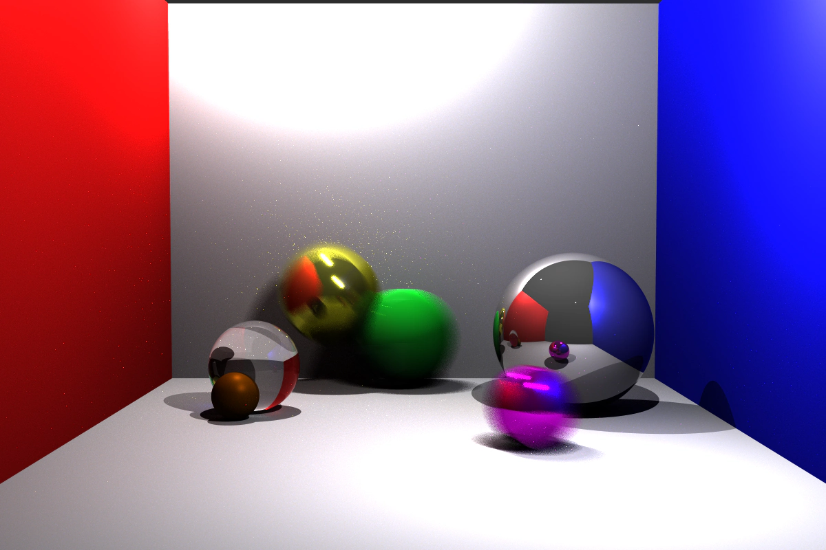
Lastly, while not visual, a big chunk of the effort in this project is keeping the rendering time down. Each step in the pipeline adds realism, but also more computation. The main techniques cut out large chunks of work—for example, finding which primitives a ray might hit can be sped up by pruning branches of the scene, so we don't need to check every primitive.
I hope you enjoyed looking at these images as much as I enjoyed making them.
Here is a video of me making the raytracer in wintry Edinburgh.
Obsessively,
Tomas